




Preventing LNG boil off ranks among the top safety and efficiency priorities in modern LNG engineering. Formed after external heat vaporizes the cryogenic liquid, boil-off gas must be managed,captured, or vented, with each option carrying safety, environmental, and economic implications. Among available solutions, vacuum insulated piping addresses this challenge at its source, offering measurable advantages when compared to conventional insulation PUF (Polyurethane Foam).
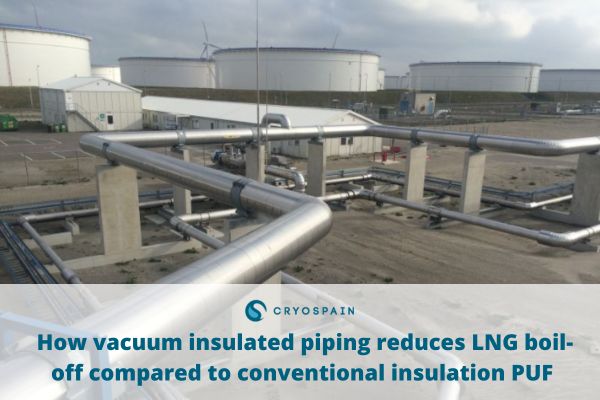
Specialized cryogenic pipes play a key role in facilitating the safe and efficient movement of LNG between storage, transport, and end-use points as part of LNG transfer lines, loading arms, bunkering lines and run-down lines.
In a context where every heat leak in cryogenic piping leads to inefficiencies, how does conventional conventional insulation PUF compare to vacuum insulated piping? And what specific measures can engineers apply to control and reduce heat ingress in LNG transfer lines? Let’s take a look.
Understanding LNG boil-off in cryogenic pipes
What is LNG boil-off and why does it occur?
LNG boil-off is the vaporization of liquefied natural gas. It occurs when heat from the environment penetrates the LNG storage or transport system, turning a portion of the liquid back into gas (through a vaporization process).
In LNG systems, boil-off is fundamentally a heat-balance outcome: heat from the environment migrates through the insulation; once it reaches the liquid at a cryogenic temperature (-162°C), that energy is “spent” primarily on latent vaporization, converting liquid LNG into gas rather than increasing its temperature. Any remainder is allocated to sensible heating or flashing, depending on the system’s pressure and enthalpy state.
In cryogenic pipes, boil-off occurs for two main reasons:
- Distributed heat leaks along the line warm the liquid and drive local evaporation. This heat ingress in LNG transfer lines scenario is particularly common during steady transfer and especially in slow-flow or recirculation/keep-cold modes.
- Process-induced phase change as a result from pressure/enthalpy. A change that can be driven by factors such as hydrostatic pressure changes in vertical pipe runs, throttling or pressure drops, or heat originating from friction in pumps or lines; all of which can trigger local boiling or flashing even when insulation is good.
Why is LNG boil-off a critical issue for operational efficiency and cost control?
Heat ingress in LNG transfer lines and other cryogenic pipes represents an important compromise when it comes to safety and operational expenditure (OPEX) in LNG projects:
- From a security standpoint, the continuous generation of boil-off gas increases pressure in tanks and connected systems. Because of this, LNG boil-off handling is embedded in prevailing safety standards and codes, such as the National Fire Protection Association standard NFPA 59A.
Depending on each facility’s design and particular scenario, safety handling may involve fuel use, reliquefaction, compression/return, controlled venting or flaring.
- In terms of operational efficiency and costs, many published analyses consider LNG boil-off losses during transfer and other operations as a significant cause of negative economic and environmental impacts.
In practice, BOG must be understood either as a loss or as an additional workload: even if vapour is recovered rather than vented, the equipment must compress, reliquefy and consume it, all of which implies additional power and added maintenance complexity.
In contrast to this, insulation choices that reduce LNG boil-off during transfer and other operations have direct implications for efficiency and operational expenditure (OPEX), as they translate into smaller, safer vapour-handling duties and improved operability.
You might be interested: Everything you should know about storing liquefied natural gas (LNG)
How does insulation influence LNG boil-off rates in cryogenic piping systems?
Achieving thermal efficiency in cryogenic piping reduces LNG boil-off rates byinhibiting the main mechanisms that enable heat ingress from taking place. When insulation is well designed, it can lower the rate of vapor generation and, as a consequence, reduce the burden on pressure-control and vapor-return systems.
In order for minimal cryogenic pipe heat transfer rates to occur, it’s key that LNG insulation considers system assemblies in their entirety while also addressing all possible mechanisms of heat ingress.
What are the mechanisms that cause heat ingress in cryogenic piping insulation for LNG?
- Heat ingress: heat can go through the insulation system via thermal conductivity, convection or radiation, increasing the liquid’s enthalpy and producing a two-phase flow. For conventional cold-service insulation (including polyurethane and polyisocyanurate foams, mineral wool systems with vapour barriers, cellular glass, etc.), the dominant thermal path is typically conduction through the insulation material. External convection and radiation are also present at the outer surface, with “parasitic” heat leaks through supports, penetrations, and joints also being an issue.
- Cool-down transients: before steady operation can be achieved, warm pipework must be cooled to cryogenic temperature. If not controlled, this phase can produce significant BOG.
- Elevation or pressure effects: in upward transport operations, reduced hydrostatic pressure at elevated points can promote local boiling.
- Pump shaft power and frictional dissipation: pumping and turbulent flow add heat, contributing indirectly to vapour generation. In fact, several LNG bunkering and transfer studies explicitly identify pipe heat ingress and pump heat as BOG drivers.
Keep reading: Cryogenic systems for LNG fuel on ships: design, materials, and safety considerations
What factors influence LNG boil-off rates in piping insulation?
Boil-off rates in LNG pipe insulation are influenced by a set of thermal, hydraulic, and operational variables, including:
- Overall heat transfer coefficient (U-value) and linear heat leak or heat flux (W/m) of installed systems as a whole (including insulation, cladding, joints, valves and supports). Geometry and construction details must not be underestimated here, considering how the cryogenic engineering literature and vendor data commonly represent vacuum-insulated piping performance directly as heat leak per unit length (W/m).
- Insulation material properties and thickness. conventional insulation PUF commonly presents a lower thermal conductivity (often reported around ~0.02–0.03 W/m·K in general materials literature). However, considering the importance of system-level heat leaks, material properties must be evaluated alongside other factors such as installation quality and thermal bridges.
- Moisture ingress and vapour barrier integrity. For cold piping, any moisture entering the insulation system tends to condense and freeze within the assembly. This can degrade performance and cause mechanical and safety problems.
- Length, diameter, fittings, and “lumped” heat loads. When applied to valve boxes, flanges, bayonets and other instruments, these issues can dominate system losses provided they are not insulated to the same standard as straight runs.
- Flow rate and operating mode. When comparing steady transfer vs low-flow standby, heat ingress per unit mass transferred increases when flow rate is low or dwell time in the line is long.
- Ambient conditions. Air temperature, wind, solar loading, rain and proximity to seawater can all affect outer-surface convection and, for some systems, long-term integrity.
The role of insulation in reducing heat ingress in cryogenic pipes
Cryogenic pipe insulation reduces heat by protecting cryogenic fluids from heat ingress, addressing the main mechanisms and factors outlined above.
As such, effective insulation systems must be capable of:
- Lowering effective thermal conductivity.
- Increasing thickness.
- Reducing thermal bridges.
- Maintaining integrity of vapour barriers and cladding over time.
By reducing heat ingress in LNG transfer lines, steady vapour generation is reduced, but the benefits extend further: vapour-return and pressure-control duties are minimized, and cool-down behaviour is shortened or stabilized as the total external heat load requiring management is reduced.
Vacuum insulated piping vs conventional insulation PUF: a LNG pipe insulation comparison
The difference between foam and vacuum insulated piping for LNG lies in each method’s approach: while foam resists and blocks heat, vacuum works by removing its medium.
Also known as vacuum jacketed pipe or pipe-in-pipe VIP/VJP, these systems consist of a cold inner pipe housed within an outer jacket, separated by an evacuated annular space. The vacuum in this annular space is the key that unlocks this structure’s advantages: under high vacuum, convection and residual gas conduction are strongly suppressed.
In doing so, vacuum insulated piping for LNG reduces LNG boil-off by targeting two mechanisms that conventional conventional insulation PUF cannot simultaneously tackle: convection and conduction.
In this context, radiation and solid conduction through supports and spacers become the dominant remaining heat paths.
In order to reduce radiative heat transfer, vacuum systems typically include multilayer insulation (MLI) or radiation shields. A formula supported by CERN documents addressing cryogenics, as well as NASA publications describing MLI and vacuum effects and other additional peer-reviewed studies.
As such, vacuum insulated piping for LNG represents a fundamental shift in how heat ingress is prevented, translating into a series of distinctions when comparing vacuum insulated piping vs conventional insulation PUF:
Comparative thermal performance and boil-off reduction of vacuum insulated pipe vs conventional insulation PUF
- Insulation principle: conventional insulation PUF relies on low bulk thermal conductivity (k) and thickness; vacuum insulated pipes rely on the properties of high vacuum as well as multilayer insulation (MLI) and radiation shields.
- Target heat transfer mechanisms: conventional insulation PUF reduces conduction but it still leaves external convection and radiation at the surface; vacuum insulated piping suppresses convective heat transfer in the annulus and, when coupled with MLI, can reduce radiative heat transfer substantially, achieving lower heat leak values.
- Sizing: vacuum insulated piping often achieves substantially lower heat leak at comparable or even smaller outer diameters.
- Limitations and performance dependencies: conventional insulation PUF is highly sensitive to installation quality and long-term moisture control. A key engineering distinction for LNG facilities is that foam systems can be “good on day one” but degrade if vapour barriers and cladding are breached, allowing moisture ingress and ice formation.
On the other hand, vacuum insulated piping for LNG shift the long-term risk profile: while they require vacuum quality assurance (via leak testing during fabrication, applying getters and adsorbents where needed and monitoring ports), they avoid the classic cold-service moisture pathway within thick external insulation. In other words, vacuum quality must be understood as a key performance variable vital to access this method’s benefits.
Quantifying boil-off reduction when comparing vacuum insulated piping vs conventional insulation PUF
When considering whether vacuum-insulated piping is worth it for LNG projects, one metric stands out: how much boil-off reduction can you realistically expect?
Industry comparisons offer a clear picture of LNG boil-off rate calculation expectations when comparing vacuum insulated piping vs conventional insulation PUF:
- A LNG-specific brochure produced by PHPK Technologies with Linde engineering partners states that vacuum insulated piping can deliver about 1/10th the steady-state heat leak of conventional mechanically insulated piping for LNG service. In other words, vacuum jacketed pipe heat loss presents a ~10× reduction in steady-state heat leak.
- A widely circulated LNG GHG emissions guideline from the American Petroleum Institute mentions that, in a transfer rate of 228 m³/min scenario, insulation U-values are 0.26 for foam, 0.13 for powder, and 0.026 for vacuum. The document also reports typical transfer pipe loss factors of 0.0012%/km (foam) versus 0.00012%/km (vacuum), which again represents a 10× difference in the loss factor for transfer piping under that specific example basis.
In cryogenic engineering applications outside LNG, such as transfer lines for liquid helium or nitrogen, experimental studies show that carefully designed vacuum + MLI transfer lines can reach very low heat leak values. Some experimental configurations achieve values on the order of <1–2 W/m.
Given the variability in LNG system design (with different diameter, insulation thickness, ambient exposure, valve and fitting density, flow regime, and duty cycle), universal figures and calculations are not applicable.
However, a practical engineering range distilled from specialized industry publications is often ~5–20× lower steady heat leak (or a ≈80–95% reduction) when comparing vacuum insulated piping vs conventional insulation PUF. As seen above, many LNG references support ~10× as a representative figure for well-designed systems.
This 10x reduction in cryogenic insulation performance can have significant implications for any installation: for a one-off transfer of 130,000 m³, those factors would correspond to about 15.6 m³ vs 1.56 m³ of potential transfer loss. In facilities where vapour is often captured and handled, these figures would still make a major difference, considering the energy and handling duty of the boil-off would still need to scale to the volume of boil-off generated. In this scenario, conventional insulation PUF would mean ten times more vapour to handle, with the corresponding impacts on equipment sizing, power consumption, and system complexity.
Converting heat leak into LNG boil-off: a practical case study
While comparing insulation systems in W/m is useful from a purely engineering standpoint, decision-makers usually require a more operational interpretation of those thermal losses.
In this section, we focus on the most technical and quantitative data. We also examine how heat ingress translates directly into LNG boil-off, affecting vapour generation, product losses, BOG system sizing, and operating costs.
The Rotterdam GATE bunkering project operated by Cryospain provides a rigorous technical benchmark for quantifying this effect.
The installation consists of approximately 790 metres of vacuum insulated piping in DN 300, DN 150 and DN 100, designed for continuous liquid LNG service. Using validated design heat-leak values, vacuum insulation (VIP) performs at approximately 1.5 W/m, compared with around 25 W/m for equivalent foam-insulated piping. On this basis, total steady-state heat ingress decreases from approximately 19 kW to 1.2 kW, which corresponds to a 94% reduction in thermal load.
This thermal differential is the basis for all subsequent calculations in mass loss, energy balance, and emissions impact.
When converted using LNG’s latent heat of vaporization (460 kJ/kg), the reduced heat ingress translates into approximately 1,140 tonnes of LNG preserved per year. This corresponds to around 2,500 m³ of liquid LNG, or roughly 1.6 million standard m³ of natural gas that is no longer subject to boil-off, venting, reliquefaction, or flaring processes.
At a reference LNG value of €0.60/kg, this results in approximately €685,000 per year in avoided product losses, leading to a simple payback period of roughly eight months for the incremental cost of vacuum-insulated piping.
From an emissions standpoint, preventing this level of methane vaporisation avoids approximately 34,000 tonnes of CO₂-equivalent per year (using a methane GWP₁₀₀ of 29.8, IPCC AR6). In addition, the reduced heat ingress directly lowers the required capacity of vapour handling, compression, and reliquefaction systems, enabling more efficient and smaller-scale terminal design.
Cryospain case studies: reducing LNG boil-off in real-life projects
Cryospain’s extensive experience in complex cryogenic engineering spans a diverse portfolio of projects addressing LNG boil-off through tailored, proven solutions, including:
- The Rotterdam GATE Terminal LNG ship-refuelling transfer line project in the Netherlands, involving approximately 790 m of vacuum-insulated piping in DN300, DN150 and DN100, designed for LNG service . This project provides a practical reference for the heat-leak and boil-off reduction calculations discussed earlier in this article.
- LNG bunkering port terminals on Spain’s Cantabrian coast (Bilbao and Santander), where Cryospain designed and manufactured ~1.5 km of vacuum insulated piping connecting storage plant to jetty loading/unloading. A project where technology was specifically designed to limit gasification during transfer due to high thermal efficiency, following design to ASME B31.3 with design pressure up to 19 bar.
- Three LNG marine fuel system projects for sister ships built by Fincantieri in Italy, involving the supply of more than 4.5 km of vacuum-insulated piping, from DN40 to DN450, for onboard LNG fuel transfer. This reference highlights Cryospain’s experience in large-scale marine cryogenic piping systems designed to reduce heat ingress and limit LNG boil-off.
From bunkering terminals to ship retrofits and kilometre-scale piping, this wide range of projects demonstrates LNG boil-off doesn’t have to be a given in cryogenic pipe insulation.
Ready to tackle LNG boil-off with top engineering precision? Our expert team brings deep cryogenic expertise to every project and a tailored approach to meet every LNG system’s unique thermal demands.
Want to learn more about how cryogenic technology can transform your operations? Get in touch with Cryospain’s team of experts.